 |
|
|
|

|

|
Elisha Kally’s water flow calculator |
|
|
|
|
|
|
Elisha Kally was, by all accounts, a very innovative engineer; it shouldn’t surprise us that the slide rule he designed in 1958 is an unusual one. And it is... very unusual. |
|
|
|
 Click photo to enlarge |
|
|
|
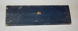
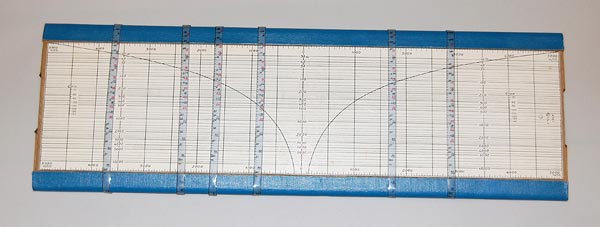
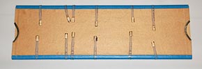
This large (41x13 cm) calculating device consists of a base, a wide slide that moves right and left in it, and six transparent bands that encircle the whole thing like rubber bands. Or they did once; now each is missing a short section in the back, and judging by the broken edge I surmise this section was in some elastic material that provided tension to keep the bands taut. When whole, each band could be made to slide right or left but also rotate along its length to move the scales on the band up and down relative to the slide. |
|
|
|
 Click a photo to enlarge |
|
|
|
 Click photo to enlarge |
|
|
|
And what was the purpose of this weird contraption? I’d never have guessed if the case it came in hadn’t contained a somewhat tattered Hebrew instructions manual, whose scan you can see here. This teaches us that we have here an “instrument for calculation of water supply networks”, which is based on the Hazen Williams formula. This formula is well known (at least to water engineers it is); it is an empirical formula which relates the flow of water in a pipe with the physical properties of the pipe and the pressure drop (“hydraulic head loss”) caused by friction. In fact, I have another slide rule that is based on this formula, made (also in 1958!) by P.J.S. for the Stanton Ironworks Company in England, and you can see in the photo that it is far less sophisticated than the Kally device. The same is true of two other Hazen Williams slide rules I’ve come across. |
|
|
|
 Click photo to enlarge |
|
|
|
The Kally calculator is more complicated
because while the others simply compute the flow in a single length
of pipe, Kally’s calculator does something way more ambitious: it
can compute all at once the flows in an entire network
consisting of up to six pipes of different diameters and lengths,
with up to six inputs and outputs, hooked up in series or in complex
ring-like arrangements. In other words, the P.J.S. slide rule can answer questions like: “Given a concrete pipe of 6” diameter at a hydraulic gradient of 20 ft/1000 ft, what will the flow in Gallons per minute be?” But the Kally slide rule can answer this: “Given a 4” diameter pipe 100 m long, connected to a 6” pipe 100 m long, connected to an 8” pipe 500 m long, connected to a 12” pipe a kilometer long, with a pump at one end pushing 280 cu.m./hour and a reservoir at the other end, and with outlets at the junctions of each two pipes drawing 50, 150 and 100 cu.m./hr respectively, what will the hydraulic head loss and the flow rate in each pipe segment be?” See the difference? To effect such a
calculation you go through a two-step process: first you set up the
bands to represent the parameters of the pipes in the system – one
band per pipe. Then you move the slide to a position determined by
the pump’s output. That done, the slide rule now represents your
entire system and you can simply read the head loss and flow in each
of the pipes at the intersection of its band with the curve on the
slide. For rings and more complex systems the process is more
complicated – but not by much. |
|
|
|
Two steel pipes connected in series: Pipe 1 has a diameter of 12” and a length of 100 m, Pipe 2 is 24” and 500 m. A pump pushes 1800 cu.m./hr into pipe 2; a valve at the junction of the two pipes pulls 500 cu.m./hr; and the far end of pipe 1 feeds the remaining water into a reservoir. Find the head loss in the two pipes, and the flow rate into the reservoir. |
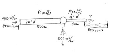
|
|
|
|
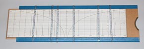
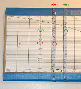
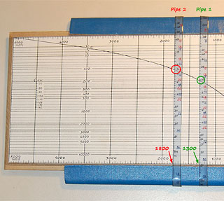
The photos below show how to solve this (click each photo for a larger annotated version). |
|
|
|
 Click a photo to enlarge |
|
|
|
Step 1 (photo on left): Set up two bands, one for each
pipe, as follows:
Step 2 (photo on right):
From the second photo you can see, then, that the answer is: Pipe 2 will carry 1800 cu.m./hour (small wonder – that’s what the pump pushes into it...) and have a head loss of 3.8 m, and pipe 1 will carry 1300 cu.m./hour and have a head loss of 9.5 m. What’s more, if you wanted to explore how using a stronger pump would affect these data, you’d merely move the slide and read out the new numbers! |
|
|
|
He was a key player in the “National Water
Carrier” built to carry water from the Sea if Galilee to the Negev
desert, and had later played a role in the water part of the peace
negotiations in the nineties and in the unrealized plan for a canal
between the Red and the Dead Seas. His engineering ingenuity is best appreciated, however, from the following story. In 1948 he found himself in a bomb shelter in a besieged Kibbutz under Egyptian bombardment. Kally provided illumination for the underground shelter by rigging up a mirror that reflected the sun’s rays; and to make the mirror track the sun’s path in the sky, he built an improvised tracking system from two halves of a barrel, with water dripping from the full half to the empty one, thus raising a floater that moved the mirror. That’s engineering at its best: “Making what you want from things you can get”. I like Elisha Kally, and I like his slide rule! |
|
|
|
Exhibit provenance: A lucky day at the Jaffa flea market. More info:
|
|
|
|
|
|
|
|
Home | HOC | Fractals | Miscellany | About | Contact Copyright © 2012 N. Zeldes. All rights reserved. |
|
