 Home
Home
 Up
Up
|
|
|

|
Washington Sabatini’s impressive calculator |
|
|
|
|
 Click photo to enlarge |
|
|
|
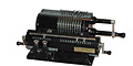
This impressive device, the Ferrero H 39
circular slide rule, was developed in Italy by Washington Sabatini
in the 1930’s. Its function is explained clearly in the Italian
manual:
The purpose of the “WASHINGTON” calculators is to give engineers a quick and certain means of calculating the dimensions of reinforced concrete structures used in construction. It is also a means of relieving them from arithmetic and allowing them to choose the cheapest sections. In this way the efficiency of their work increases as well as the possibility of realizing considerable savings in the material.I wouldn’t take Mussolini’s word for it (however powerful a driver he may have thought himself), but there is no question that the Washington is one impressive productivity booster. Construction:
At 27 cm diameter, this is one of the largest items in my
collection. It comprises ten concentric aluminum rings covered with
complicated scales and pointers. The rings are all movable except
for the second largest; that one is fixed to the body of the device,
as is the celluloid cursor overhanging the largest ring. The movable
rings are rotated around the center of the device by use of the
prominent crank handle that spans its radius. |
|
|
|
 Click photo to enlarge |
|
|
|
Each ring carries a number of scales, and between one and three indices (the pink circles with a pointer) that point to the scale on the next larger ring. The multiplicity of scales and indices is due to the many types of concrete structures that can be calculated: rectangular beams, T beams, pillars, etc. Tiny icons reflecting the respective shapes tell you which calculation each index or scale is to be used for. |
|
|
|
The identities of the various scales are given
in a detailed foldout page in the manual. They represent loads,
dimensions, moments, stresses, and other parameters that I would no
doubt appreciate were I a civil engineer. The bottom of the instrument is closed by a round plate that also carries four rubber feet; when you remove the plate you can see the complex baseplate that holds the rings snugly in their orbits. |
 Click photo to enlarge |
|
|
|
This baseplate has grooves where spring-loaded retainer pins both guide and constrain each ring’s motion. In the close-up photo you see some of these retainers, as well as the screws that hold the slotted domes in place. The screw at the left edge of the photo, beyond the grooves, fastens the fixed ring to the baseplate. |
|
|
|

 Click a photo to enlarge |
|
|
|
The calculator comes in an octagonal padded
box, and in its lid are fitted two aluminium arcs that are plug-in
additions to the scales in the fifth ring, where they can be secured
with two pins that fit small holes on that ring. Operation: To
effect a calculation, the rings are all engaged to the crank, which
is then turned to set each of them in turn -- going from the outside
towards the center -- to point to the correct value on the next
larger ring. After each ring is set its button is raised to
disengage it from further motion. When all rings have been set, the
wide outermost ring that has been carried with the crank throughout
this exercise will be found -- mirabile dictu! -- to show the correct
result under the cursor’s hairline. |
 Click photo to enlarge |
|
|
|
Problem: Calculate the height of a
rectangular beam of 6 meter span which must withstand a load
(including its own weight) of 12,000 kg. Assume a bending moment
coefficient of 1/8, permissible stress of cement and iron 50 and
1400 kg/cm2 respectively, a modular ratio of 10 and a beam width of
30 cm. Preparation: Lower all buttons and turn the crank full circle to engage all the rings. |
|
|
|
 Click photo to enlarge |
|
|
|
Step 1: Rotate the crank to bring the P index [Total load] to 12,000 kg and raise the P button. |
|
|
|
 Click photo to enlarge |
|
|
|
Step 2: Bring the L index [Beam span] to 6 m and raise the L button. |
|
|
|
 Click photo to enlarge |
|
|
|
Step 3: Bring the M index [Bending moment coefficient] to PL/8 and raise the M button. |
|
|
|
 Click photo to enlarge |
|
|
|
Step 4: Bring the Sigma index for rectangular beams to the intersection point of the arc 1400 [permissible stress of iron] with the curve 50 [permissible stress of cement] on the scale with a white background (the blue background is for iron calculations) and raise the Sigma button. |
|
|
|
 Click photo to enlarge |
|
|
|
Step 5: Raise the m button [Modular ratio] -- the
index is already on the value 10 so no rotation is required for this
ring. Step 6: Raise the s button. This parameter is not used in the calculation of rectangular sections; for such sections the two black arrows must always coincide, and since they do, no rotation is required for this ring. Step 7: Bring the b index [Beam width] to the value 30. |
|
|
|
 Click photo to enlarge |
|
|
|
Step 8: Since the ::: index [Percentage of reinforcement in compression relative to that in tension] is already at zero, as it should be (there is no need for reinforcement in compression), this ring is left alone. |
|
|
|
Step 9: The
result can now be read under the cursor’s hairline on the outer
ring. This ring has multiple scales, whose purpose is indicated by
marks placed on the cursor itself. Here we use the outermost scale,
marked "h" (beam height) on a rectangular icon (rectangular beam). The
celluloid has yellowed, but this is clear if you enlarge the photo.
The result, under the hairline, is 70 cm. That’s it! And if you think that was difficult, remember that we’ve just solved an equation with seven variables -- try that with pencil, paper, and a standard slide rule! The Duce, it seems, got it right that time: every construction engineer would benefit greatly from Sabatini's invention. |
 Click photo to enlarge |
|
|
|
The inventor: Washington Sabatini
(1890-1966) was a civil engineer from Oneglia in northern Italy. He
served in the first world war as an officer in the Italian
Engineering Corps, and subsequently applied himself to the
development of calculating aids for reinforced concrete problems. He
produced three calculators in this domain: the first model (seen
here) came out in the mid 1920s, the second (here)
around 1929, and the H 39 -- the device shown in this article --
arrived in the late 1930s (my unit’s manual was printed in September
of 1939). |
|
|
|
Exhibit provenance: eBay, from a seller in Romania.
More info: The French version of Sabatini’s patent for this device, issued in 1938. |
|
|
|
|
|
|
|
Home | HOC | Fractals | Miscellany | About | Contact Copyright © 2021 N. Zeldes. All rights reserved. |
|